+86-13676695112
+86-18868136522
+86-576-87733908
Selecting a pump based on flow rate alone is one of the more predictable ways to create a system that runs inefficiently, costs more to operate than it should, and may still fail to meet process requirements. Engineers evaluating Pressure Gear Pump options often encounter this tension: the instinct to choose a higher flow rating for safety margin collides with the engineering reality that oversizing a pump introduces its own set of problems. Getting the flow rate right — not high, not low, but matched to what the application actually demands — is where the selection process either serves the system well or undermines it from the start.
Flow rate in a gear pump is the volume of fluid delivered per unit of time. In a gear pump, this output is determined primarily by two variables: the displacement per revolution — determined by gear geometry, specifically tooth profile and the space between gear teeth — and the rotational speed driven by the motor or prime mover.
The relationship is direct: larger displacement per revolution at the same speed produces higher flow. Higher speed at the same displacement also produces higher flow. Both variables have practical limits. Displacement is fixed by the pump model selected. Speed can vary within a range, but driving a gear pump above its rated speed causes cavitation, accelerated wear, and eventually mechanical failure.
This means that for a given pump model operating at a given speed, the flow rate is relatively predictable — it does not fluctuate dramatically unless the fluid viscosity changes significantly or the back-pressure on the pump outlet increases to the point that internal slip becomes substantial. Understanding that predictability is the foundation of accurate pump selection.
The intuition to select a pump with higher flow than the application strictly requires — to build in margin — is understandable. But oversizing a Pressure Gear Pump creates a specific set of operational problems that erode any safety benefit the extra capacity was supposed to provide.
Excess flow requires throttling. If the pump delivers more fluid than the system needs, the excess must go somewhere. Typically it is recirculated through a bypass valve or throttled at a control point. That throttling converts hydraulic energy into heat. The heat goes into the fluid, raising its operating temperature, increasing viscosity change risk, and accelerating degradation of both the fluid and the seals.
Energy consumption rises with displacement. A larger pump draws more power to move its gear volume through each revolution, regardless of whether the system needs all that fluid. The energy used to pump fluid that is simply recirculated is wasted every operating hour, compounding into significant cost over the equipment's service life.
Component wear accelerates at high bypass fractions. Bypass valves and relief valves that operate continuously — rather than as emergency devices — wear faster than those used intermittently. A relief valve sized for a large pump and cycling constantly is a maintenance liability rather than a safety feature.
Pressure transients become harder to manage. A large pump generating flow that the system cannot absorb quickly produces pressure spikes on startup and shutdown. These spikes stress seals, joints, and downstream components in ways that a correctly sized pump would not.
The conclusion is not that margin is wrong — a modest safety margin above calculated flow is sensible. The problem is large oversize margins that produce chronic bypass operation.
Every application that uses a Pressure Gear Pump has a flow requirement that can be defined from the process parameters. The challenge is that those parameters are sometimes poorly characterized before the pump is specified, which is why oversizing becomes a default — it feels safer than under-specifying.
A structured approach to application-based flow determination involves:
Identifying the fluid being handled. Viscosity directly affects the pump's volumetric efficiency — the ratio of actual output to theoretical displacement. High-viscosity fluids tend to reduce slip past the gear teeth, which can improve volumetric efficiency at low speeds but creates higher inlet pressure requirements that affect sizing. Low-viscosity fluids increase internal slip, particularly at high back-pressures, meaning the actual output at pressure may be noticeably lower than the theoretical displacement.
Defining the required flow at the point of use. What volume of fluid must arrive at the process point per unit time? This is the process flow requirement, independent of pipe losses and pump efficiency. For lubrication systems, it is the oil volume needed to maintain film thickness across all lubricated surfaces. For fuel transfer systems, it is the transfer rate required to meet fill time targets. For hydraulic circuits, it is the flow needed to achieve cylinder or motor speeds within the cycle time.
Adding line losses and efficiency corrections. Between the pump outlet and the point of use, pressure drop through pipes, fittings, filters, and heat exchangers consumes driving pressure and may require higher flow to compensate for fluid that bypasses internally at operating pressure. These corrections convert the process flow requirement into the pump delivery requirement.
Applying a reasonable design margin. A modest allowance above the calculated pump requirement accounts for variation in operating conditions — fluid viscosity changes with temperature, process demands may peak slightly above average. This margin should be based on the actual range of variability, not on a general sense of caution.
Flow rate and operating pressure are linked in gear pump selection in ways that make it impossible to specify one correctly without considering the other. A gear pump selected for its flow output at low pressure may deliver significantly less actual flow at the higher back-pressure of the real system.
The mechanism is internal slip — fluid that leaks from the high-pressure outlet side back toward the low-pressure inlet side through the clearances between gears and pump housing. At low pressure, slip is minimal and actual output approaches the theoretical displacement. As pressure increases, slip increases, and actual output falls below the displacement calculation.
For a Pressure Gear Pump in a hydraulic circuit operating at elevated working pressure, this means the pump must be sized for the flow needed at operating pressure — not at zero back-pressure. A pump that delivers adequate flow at low pressure may be inadequate at the system's actual working pressure.
This interaction also means that a pump selected primarily for a high pressure rating without attention to its flow output at that pressure may deliver far less flow than expected. The pressure rating describes what the pump can withstand structurally — it does not guarantee that volumetric efficiency remains high at that pressure.
Different industrial applications have characteristic flow needs that influence gear pump selection. Understanding these differences prevents applying selection logic suited to one context to an application with fundamentally different requirements.
| Application Type | Flow Characteristic | Pressure Characteristic | Viscosity Range | Key Selection Priority |
|---|---|---|---|---|
| Hydraulic power units | Moderate to high flow | High pressure | Low to medium | Pressure rating and volumetric efficiency at pressure |
| Lubrication systems | Low to moderate flow | Low to moderate | Medium to high | Consistent flow at varying viscosity |
| Fuel transfer | Moderate to high flow | Low to moderate | Low | Flow stability and seal compatibility |
| Chemical dosing | Very low flow | Variable | Wide range | Precision at low displacement |
| Oil transfer and circulation | High flow | Low to moderate | Medium to high | Self-priming capability and flow at high viscosity |
| Cooling circuit circulation | Moderate flow | Low | Low | Flow consistency and low noise |
The table reflects that application type shapes which parameter deserves the most attention in selection. A hydraulic power unit selection process that does not carefully evaluate volumetric efficiency at working pressure will produce a pump that runs but underperforms. A lubrication system selection that ignores viscosity range across the operating temperature profile will produce inconsistent oil delivery — sometimes too much, sometimes too little.
Viscosity is one of the most influential fluid properties in gear pump selection, and it is also one of the most variable — the same fluid can span a wide viscosity range between cold startup and steady-state operating temperature.
At high viscosity (cold fluid, thick oils, some polymers):
Internal slip decreases — actual output approaches theoretical displacement
Inlet pressure requirements increase — the pump must work harder to draw fluid in
Startup torque increases — the motor must deliver higher torque at cold startup
Risk of cavitation on the inlet side increases if the inlet line cannot supply fluid fast enough
At low viscosity (hot fluid, light fuels, thin process fluids):
A Pressure Gear Pump specified for operation across a wide viscosity range needs to be evaluated at both extremes — not just at the nominal operating condition. The worst case for flow delivery is typically high viscosity at startup combined with elevated system pressure. The worst case for pump wear is typically sustained operation with low-viscosity fluid at high speed.
A pump that runs continuously faces different stress conditions than one that operates intermittently. Continuous duty puts sustained thermal load on bearings, seals, and the pump body. Intermittent operation creates thermal cycling that stresses the same components differently — repeated heating and cooling of metal components produces dimensional cycling that accelerates certain failure modes.
For continuous duty applications:
For intermittent duty:
A structured selection process reduces the risk of ending up with a pump that is either too large or too small for the application.
Some applications create genuine tension between flow and pressure requirements that cannot be resolved by pump selection alone. A process that needs both high flow and high pressure simultaneously places demands that a single pump model may not satisfy — high-Pressure Gear Pumps typically have tighter internal clearances that increase efficiency at pressure but reduce the feasible displacement per revolution, which limits peak flow.
In these situations, system design options include:
These system-level responses to difficult application requirements are often more cost-effective than searching for a single pump that satisfies the full requirement. A pump supplier who understands both pump selection and system integration can help identify which approach suits the specific application.
Flow rate and pressure are the headline parameters in gear pump selection, but the full selection process involves fluid compatibility, duty cycle, thermal management, shaft and mounting configuration, and long-term parts availability — factors that require a supplier with broad product range and genuine application knowledge. Xianju Liming Machinery Co., Ltd. manufactures Pressure Gear Pumps and hydraulic components for industrial fluid handling applications, with product lines covering a range of displacement sizes, pressure ratings, and configuration options suited to lubrication systems, hydraulic circuits, fuel transfer, and industrial process applications. Their engineering team can support application review and pump selection for projects where matching the pump to the actual operating conditions is critical to system performance and service life. If you are specifying a Pressure Gear Pump for a new system or evaluating a replacement for an existing installation, reaching out to discuss the application parameters is a practical way to confirm that the selected pump will perform as the system requires.
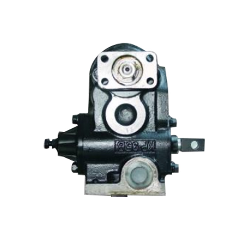
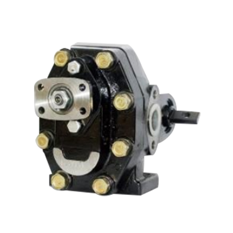
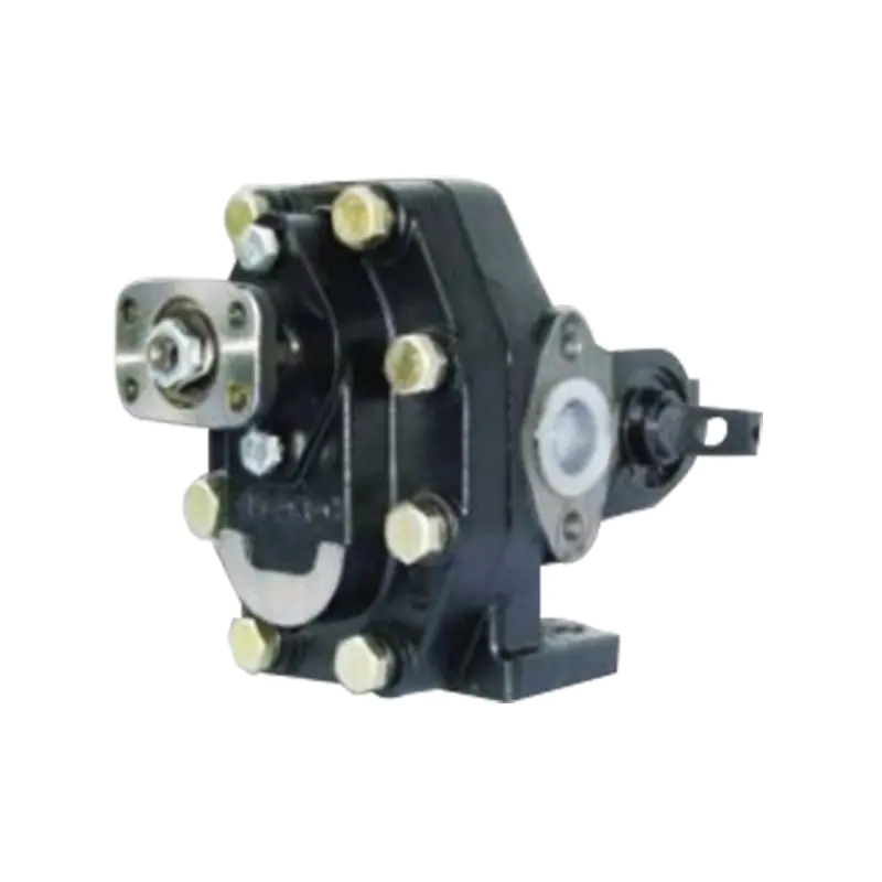
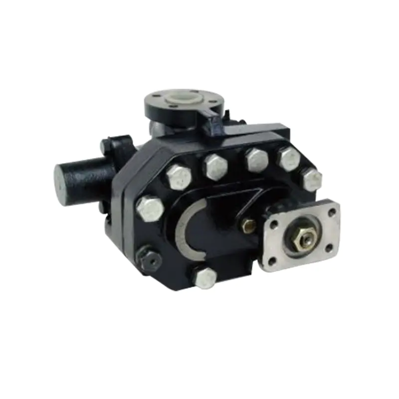
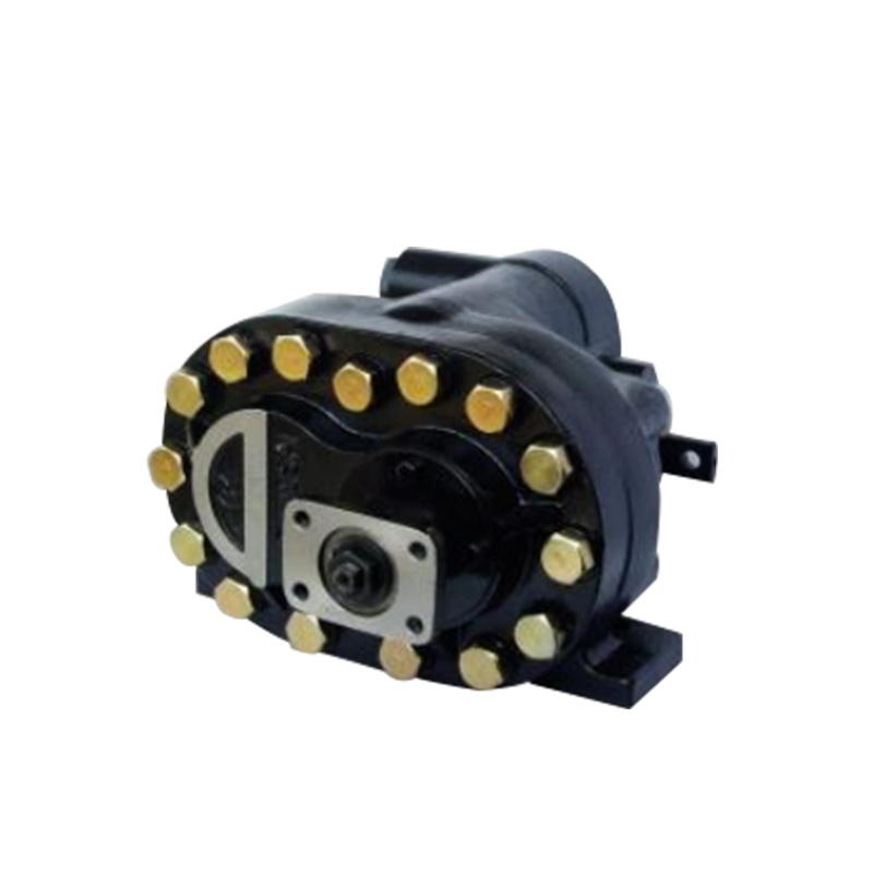
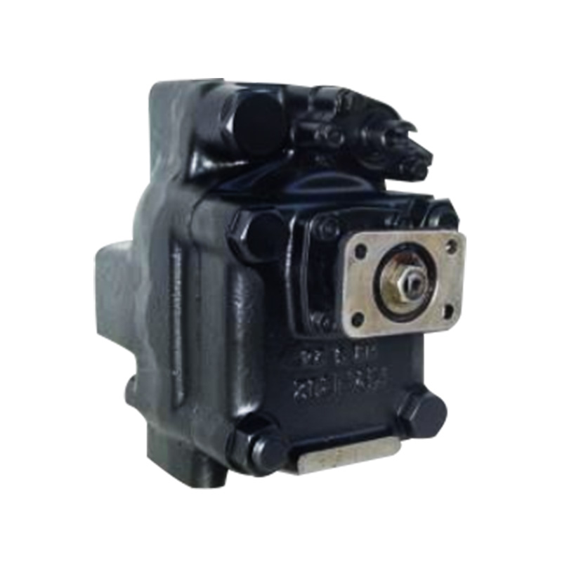
We focus on the research, development, manufacturing and service of various high-pressure and high-displacement gear pumps and related products and copper and woodblock printing machines.
Are You Ready To Cooperate
With Xianju Liming Machinery Co., Ltd. ?
* Your email is safe with us, we don't spam.
Xianju Liming Machinery Co., Ltd. specializes in the production of various high-pressure and high-displacement gear pumps and related products. We also specialize in producing various specifications of copperplate engraving machines, woodblock printing machines and other printmaking art equipment.
Contact Info
+86-13676695112
+86-18868136522
+86-576-87733908
+86-576-87719094
No. 407, Chuancheng North Road, Anzhou Street, Xianju County, Taizhou City, Zhejiang, China.
Mobile web