 English
 中文简体
中文简体
+86-13676695112
+86-18868136522
+86-576-87733908
Fluid Selection and Contamination Control
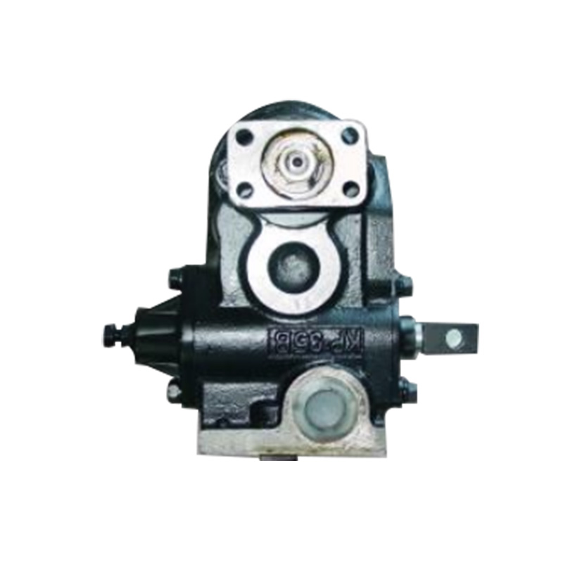
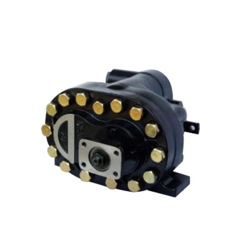
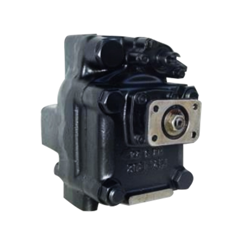
Hydraulic gear pump supplier operate with tight internal clearances—typically 0.02 to 0.08 millimeters between moving components—making them sensitive to fluid properties and contamination. Proper fluid selection and contamination control are fundamental to achieving the pump's designed service life of 8,000 to 12,000 operating hours.
Fluid viscosity is the primary consideration. Hydraulic gear pumps are designed to operate with mineral-based hydraulic fluids meeting ISO VG 32, 46, or 68 specifications, depending on ambient temperature and operating conditions. The viscosity at operating temperature must remain between 15 and 400 centistokes. Low viscosity reduces the thickness of the hydrodynamic fluid film between gear teeth and bushings, accelerating wear and increasing internal leakage. High viscosity impedes inlet flow, potentially causing cavitation and reducing volumetric efficiency. For applications with wide temperature variations, multigrade hydraulic fluids or systems with fluid heating and cooling may be necessary to maintain viscosity within acceptable limits.
Inlet Conditions and Cavitation Prevention
The inlet side of a hydraulic gear pump is often overlooked but critically affects pump performance and longevity. Inadequate inlet conditions are a leading cause of cavitation, which produces noise, reduces flow, and causes progressive damage to gear teeth and housing surfaces. Proper inlet design ensures that the pump receives an adequate supply of fluid to fill the gear cavities during each revolution.
Inlet line sizing must maintain fluid velocity below 0.5 to 1.0 meters per second, depending on the installation. Excessive velocity creates pressure drop, reducing the net positive suction head available at the pump inlet. The inlet line should be as short as practical, with minimal bends, fittings, or restrictions. Flexible hose is preferred over rigid pipe for the inlet connection, as it accommodates misalignment and reduces the transmission of vibration. The inlet line diameter should be at least one size larger than the pump inlet port—for example, a pump with a 1-inch inlet port should have an inlet line of at least 1.25 inches in diameter to maintain acceptable velocity.
Inlet strainers, while necessary to prevent large contaminants from entering the pump, must be sized to avoid excessive pressure drop. Coarse strainers with 100 to 150 mesh openings are recommended for gear pump inlets. Strainers should be inspected and cleaned regularly, as accumulated debris increases restriction over time. For systems requiring fine filtration, the main filter should be placed on the pressure side of the pump, not the inlet. Some applications incorporate a low-pressure priming pump to ensure adequate inlet flow, particularly in systems with long inlet lines, elevated inlet lifts, or cold-start conditions where fluid viscosity is high.
Mounting, Alignment, and Mechanical Installation
The mechanical installation of a hydraulic gear pump directly affects bearing life, seal integrity, and the reliability of the pump-mounting interface. Improper mounting and misalignment are common causes of premature failure, particularly in applications where the pump is driven by an electric motor or internal combustion engine through a flexible coupling.
Mounting surface rigidity is essential. The pump must be mounted to a flat, rigid surface that does not deflect under operating loads. Cast iron or steel mounting plates with sufficient thickness to resist bending are preferred. The mounting surface should be machined flat to within 0.05 millimeters per 100 millimeters of length. For foot-mounted pumps, the mounting feet must be fully supported; shimming may be required to ensure all mounting bolts are tightened without distorting the pump housing. Flange-mounted pumps require that the mating flange be square to the drive shaft axis.
Shaft alignment must be within manufacturer-specified tolerances. For flexible coupling connections, angular misalignment should not exceed 0.25 degrees, and parallel misalignment should be within 0.10 to 0.15 millimeters total indicator reading (TIR). Misalignment imposes radial loads on the pump shaft and bearings, accelerating wear and potentially causing shaft seal failure. The coupling should be selected to accommodate minor misalignment while transmitting the required torque. Gear-type couplings, while capable of high torque transmission, may transmit radial loads if misaligned and are generally not recommended for gear pump installations unless precisely aligned. Flexible couplings with rubber or polyurethane elements provide better misalignment accommodation and vibration isolation.
Startup Procedures and Operational Monitoring
Proper startup and ongoing operational monitoring are essential for achieving the designed service life of hydraulic gear pumps. The initial startup—or startup after extended shutdown—requires specific procedures to prevent damage from dry operation, trapped air, or sudden pressure application.
Pre-startup preparation begins with filling the pump housing with hydraulic fluid. The pump should never be started dry; even a few seconds of dry operation can cause irreversible damage to bushings and gear faces. If the pump has a case drain port, fluid can be introduced through this port until it emerges from the inlet or outlet. Rotating the pump shaft manually several revolutions after filling confirms that fluid has distributed through internal passages. For pumps mounted above the reservoir, a priming pump or vacuum system may be necessary to draw fluid into the pump before starting.
Initial operation should be at no load—with the pump outlet directed to tank or with system pressure relief valves fully open—for 2 to 5 minutes. This allows air to purge from the system and allows the pump to establish fluid films on bearing surfaces. During this period, listening for unusual noise is important; sharp clicking or whining indicates cavitation or aeration requiring investigation. After confirming stable operation at no load, system pressure should be increased gradually in steps, monitoring noise, temperature rise, and flow performance at each step.
Operational monitoring parameters include case drain flow, fluid temperature, and noise characteristics. Case drain flow—the fluid that leaks internally and returns to the reservoir—normally ranges from 3 to 10 percent of total pump flow at rated pressure. A gradual increase in case drain flow over time indicates internal wear; a sudden increase may signal catastrophic component failure. Case drain flow measurements should be taken with the pump operating at rated pressure and temperature for consistency.
We focus on the research, development, manufacturing and service of various high-pressure and high-displacement gear pumps and related products and copper and woodblock printing machines.
Are You Ready To Cooperate
With Xianju Liming Machinery Co., Ltd. ?
* Your email is safe with us, we don't spam.
Xianju Liming Machinery Co., Ltd. specializes in the production of various high-pressure and high-displacement gear pumps and related products. We also specialize in producing various specifications of copperplate engraving machines, woodblock printing machines and other printmaking art equipment.
Contact Info
+86-13676695112
+86-18868136522
+86-576-87733908
+86-576-87719094
No. 407, Chuancheng North Road, Anzhou Street, Xianju County, Taizhou City, Zhejiang, China.
Mobile web